Chapter 13
OVERALL APPEARANCE
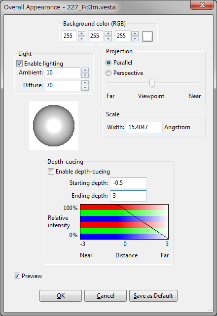
The Overall Appearance dialog box (Fig. 13.1) appears on selection of the “Overall appearance...” item under the “View” menu.
13.1 Background
The background color is specified with three values in between 0 to 255, or selected from a color selection dialog box after clicking the button at the right of the text boxes.
13.2 Lighting
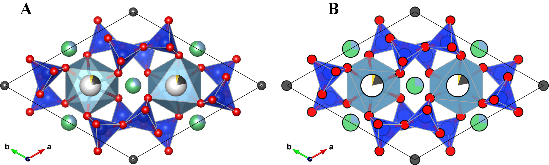
When option “Enable lighting” is checked, the following light properties are set. When lighting is disabled, the resulting figure looks like a traditional 2D plot with no gradients (Fig. 13.2).
- Ambient: A light that comes from all directions equally and is scattered in all directions equally by objects. Specified by a value in between 0 to 100.
- Diffuse: A light that comes from a particular direction and hits objects with an intensity that depends on the orientation of their surfaces. However, once the light hits a surface, it reflects evenly off a surface and radiates in all directions. Specified by a value in between 0 to 100.
- Lighting direction: This can be changed by dragging the “track ball” placed below the “Lighting” frame box.
Even though the ambient and diffuse lights are evenly reflected, some part of lights are reflected more in the manner of a mirror where most of the light bounces off in a particular direction. A light having such a reflection component is called “specular” light. In VESTA, the intensity of the specular light is fixed at 100 %, and a color of a reflected specular light, i.e., “specular color” is controlled by two properties of objects, {Specular} and {Shininess}. The final color of a surface is the sum of all three components of lights. A object surface appears to be brighter than the color of object if the specular light is reflected in the direction of viewpoint.
13.3 Projection Mode
- Parallel: Objects are rendered by parallel projection.
- Perspective:: Objects are rendered by perspective projection. Accentuation of the perspective view is controlled by the slider placed below the radio button.
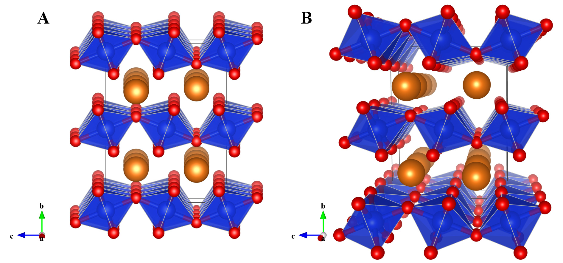
Figure 13.3 shows the structure of post-perovskite, MgSiO\(_3\) [82], visualized in the parallel and perspective modes. \begin {equation} f = \frac {end - z}{end - start} . \end {equation}
13.4 Depth-Cueing
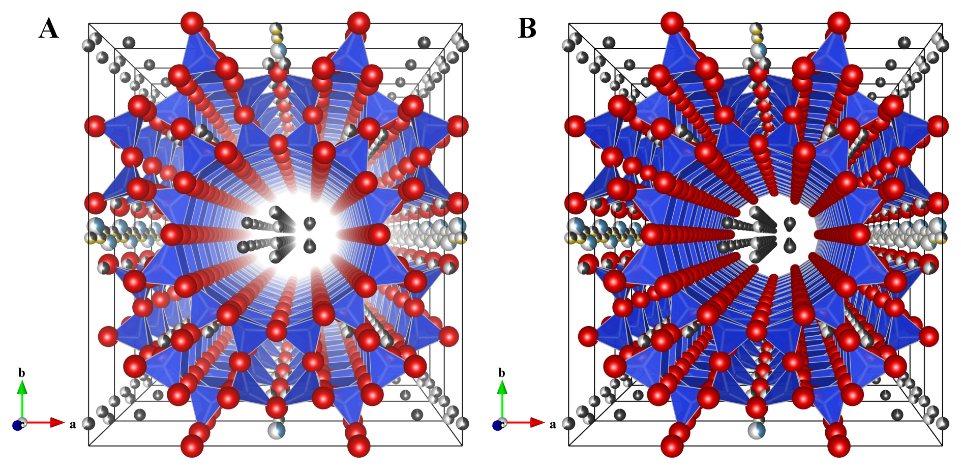
Depth-cueing blends a “fog” color with the original color of each object using the blending factor \(f\). The factor \(f\) at depth \(z\) is computed by Both of the starting depth, \(start\), and the ending depth, \(end\), are input by the user. VESTA automatically assigns the background color of the Graphics Area to the fog color \(C_f\). Then, the color of a rendering object, \(Cr\), is replaced by \begin {equation} C_r' = f*C_r + (1-f)*C_f . \end {equation} When VESTA renders objects in the Graphics Area, internal coordinates of the OpenGL scene are normalized in such a way that a radius of the bounding sphere for the scene becomes 0.9 and that the center of the scene is placed at 0. Objects at \(z < start\) are clearly rendered without any fog whereas objects at \(z > end\) are completely invisible.
Depth-cueing can be enabled or disabled in check box Enable depth-cueing. The effect of depth-cueing is schematically displayed below the two text boxes Starting depth and Ending depth.
Figure 13.4 illustrates the effect of depth-cueing on images of mordenite [83] viewed along the \(c\) axis in the perspective-projection mode.